

CAN bus is the standard for most data loggers. It uses a pair of differential wires and can work over long distances. Yellowcog’s Pilot devices work with all common CAN bus modes (up to 1MHz). The bus must be terminated at both ends with 120 ohm resistors to ensure correct operation. Note that none of yellowcog's devices provide this termination resistor so if you are connecting to a unused CAN port on a logger you must check if the logger can either be configured to provide the appropriate resistance or provide one yourself.
IMPORTANT: if you do not know the full specification of a CAN bus then any device, including all yellowcog devices, can cause the bus to fail.
Pilot uses CAN Products in many ways, including: CAN Module and CAN Serial Probe Module.
This module allows CAN to Serial back to CAN messaging to be achieved. For example, it can turn the hardware into a Serial to CAN converter allowing any CAN message to be received or transmitted from a serial window on a host machine.
NOTE: The CAN/Serial Probe module MUST be configured to have the correct messages in the configuration. The required definition of the messages depends on the operational mode and facilitates the internal operations.
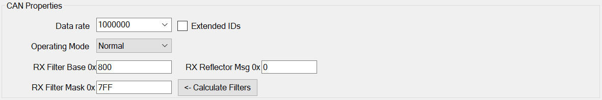
CAN Properties
Also see: CAN Endianness
The CAN bus must be configured to match the requirements of the host CAN bus. The options are:
- Data rate – fundamental to interoperability, the rate, in Hertz, that communications occurs at. All common data rates are supported.
- Extended IDs – the CAN bus specification was altered to allow a larger range of addresses to be used. To use the extended mode this checkbox should be set. It is still common to use the original mode. The only way to discover the required mode is to check the mode of the host bus via its configuration software or specification documentation etc.
- Operating Mode – this should be set to “normal”. Other modes include “Listen”, if for example no data is to be transmitted.
- Rx Filter Base – Used to define the first message number in the range Pilot™ will receive (Rx) and process.
- Rx Filter Mask – Combined with the Rx Filter Base to control processing.
The Calculate Filters button uses the currently configured receive streams to calculate the optimum receive filter. Having the wrong filter would result in missing one or all incoming packets.
CAN Serial Properties
There are two operational modes:
Serial ASCII Protocol ON
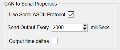
In this mode (Use Serial ASCII Protocol) any CAN message can be transmitted or received. A custom ASCII protocol is used that has the following format:
#ID,DLC,A,B...<cr>
Where:
ID = CAN message ID
DLC = Length of CAN message (0 to 8)
A,B,… = individual data bytes
So, for example, sending “100,2,1,2” would transmit a CAN message with ID 0x100, and two data bytes being 0x01 and 0x02.
Send Output Every - this time ensures that even if no CAN messages are seen on the bus there will still be a "keep alive" output on the serial port; this is useful to reassure that the probe is operational and configured. Setting this to zero will disable this functionality.
Output time deltas - when this is set an approximate time delta is added to the ASCII packet. Due to hardware constraints, the delta is only approximate and its accuracy can vary. The delta time is tagged onto the ASCII output after the last packet byte i.e. after the DLC account of comma-separated byte values.
Serial ASCII Protocol OFF
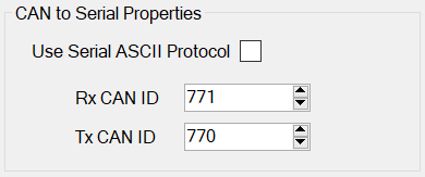
In this mode, any character received on the serial port will be encoded into a CAN message. If you send the string YELLOW into the serial port then a CAN message will be emitted as:
[TX CAN ID][6][‘Y’][‘E’][‘L’][‘L’][‘O’][‘W’]
If you send “YELLOWCOG” there will not be enough room in one standard eight-byte CAN message so two messages will be emitted, as such:
[TX CAN ID][8][‘Y’][‘E’][‘L’][‘L’][‘O’][‘W’][‘C’][‘O’]
[TX CAN ID][1][‘G’]
The exact way the message is split will depend on the (unknowable) timing of the Pilot hardware and CAN bus shift registers. As long as the data rates are sustainable then no byte will be missed.
For received CAN messages the direction is reversed. Any data received as the payload on the configured receive CAN ID will be transmitted out the serial port as the same raw binary data. e.g. if the CAN message is comprised of ASCII viewable characters then you will get out will be readable text.
Basic Properties
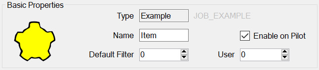
All modules have this panel. Options are:
- Type – is determined when first adding the module and governs which module properties can be configured.
- Name – used to identify the module in the module list but may also play a part on the embedded device, for example it may be required for it to appear in the outputted data.
- Enable on Pilot – if this is set then this config item will be included and enabled when transferred to the Pilot. If not, then it will still be editable on the PC but will not be used by the Pilot.
- Default Filter – see Streams, Advanced Concepts.
- User Number – This can be used to identify this module elsewhere in the system. For example, by outputting this number whenever the device is connected. In general, it can be left as zero.